The DXF exporter is based on the BOM and Gerber HID's.
I have copied the bom.c file and added portions from gerber.c and edited the used bits for DXF relevant code.
Copyright (C) for BOM and Gerber HID parts by their authors.
Some notes about Coordinate systems:
The installation and subsequent use of the DXF HID requires recompilation of the pcb package with the pcb-dxf-HID package merged into pcb. This requires the following actions:
tar -xzf pcb-dxf-HID.tar.gz
AC_MSG_CHECKING([for which exporters to use])
AC_ARG_WITH([exporters],
[  --with-exporters=       Enable export devices: bom dxf gerber png ps [[default=bom dxf gerber png ps]]],
[],[with_exporters=$hid_exporters])
AC_MSG_RESULT([$with_exporters])
for e in `echo $with_exporters | sed 's/,/ /g'`; do
    case " $hid_exporters " in
      *\ $e\ * )
        HIDLIST="$HIDLIST $e"
        ;;
 ) AC_MSG_ERROR([$e is not a valid exporter]) ;;
    esac
done
EXTRA_LIBRARIES = \
        libgtk.a liblesstif.a libbatch.a \
        liblpr.a libgerber.a libbom.a libdxf.a libpng.a libps.a
...
EXTRA_DIST= \
        check_icon.data \
        default_font \
        /hid/bom/hid.conf \
        /hid/dxf/hid.conf \
        /hid/gerber/hid.conf \
        ...
...

libdxf_a_SOURCES = \
        hid/hidint.h \
        hid/dxf/dxf.c
./autogen.sh from the pcb/ toplevel directory. ./configure with the arguments that best fit to your needs. make src ./pcb File/Export Layout/dxf or any other exporter you want to export with. make install from the toplevel directory if you want this version of pcb to be installed. doxygen dxf-dox-no-call-graphs.dox or doxygen dxf-dox-with-call-graphs.dox in the src/hid/dxf directory to create HTML, latex and other docs in the pcb/src/hid/dxf/doc directory.
The following function hierarchy, with the status of the functions in between [], exists:
Definition in file dxf.c.
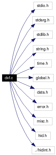
#include <stdio.h>
#include <stdarg.h>
#include <stdlib.h>
#include <string.h>
#include <time.h>
#include "global.h"
#include "data.h"
#include "error.h"
#include "misc.h"
#include "hid.h"
#include "../hidint.h"
Include dependency graph for dxf.c:

Go to the source code of this file.
Data Structures | |
| struct | Aperture |
| Aperture properties. More... | |
| struct | Apertures |
| List of apertures. More... | |
| struct | DxfPendingDrills |
| Drill (hole) properties. More... | |
| struct | hid_gc_struct |
| Definition of graphic context for the dxf HID. More... | |
| struct | _StringList |
| List with string data. More... | |
| struct | _DxfList |
| List with pcb element header data. More... | |
Defines | |
| #define | CRASH fprintf(stderr, "HID error: pcb called unimplemented DXF function %s.\n", __FUNCTION__); abort() |
| Error handling of not yet implemented functions. | |
| #define | DXF_X(pcb, x) ((long) ((x) / 100)) |
| Dxf X-coordinate (in mil). | |
| #define | DXF_Y(pcb, y) ((long) (((pcb)->MaxHeight - (y))) / 100) |
| Dxf Y-coordinate (in mil). | |
| #define | DXF_XOffset(pcb, x) ((long) ((x) / 100)) |
| Dxf X offset (in mil). | |
| #define | DXF_YOffset(pcb, y) ((long) (-(y) / 100)) |
| Dxf Y offset (in mil). | |
| #define | DXF_ROUND(x) ((int)(((x) + 50) / 100) * 100) |
| #define | DEBUG 1 |
| Debugging on/off switch. | |
| #define | DXF_COLOR_BYBLOCK 0 |
| DXF color definition, entities with this color follow the color definition of the block in which it lives. | |
| #define | DXF_COLOR_RED 1 |
| DXF color definition, pen number "1" in the virtual pen-plotter. | |
| #define | DXF_COLOR_YELLOW 2 |
| DXF color definition, pen number "2" in the virtual pen-plotter. | |
| #define | DXF_COLOR_GREEN 3 |
| DXF color definition, pen number "3" in the virtual pen-plotter. | |
| #define | DXF_COLOR_CYAN 4 |
| DXF color definition, pen number "4" in the virtual pen-plotter. | |
| #define | DXF_COLOR_BLUE 5 |
| DXF color definition, pen number "5" in the virtual pen-plotter. | |
| #define | DXF_COLOR_MAGENTA 6 |
| DXF color definition, pen number "6" in the virtual pen-plotter. | |
| #define | DXF_COLOR_WHITE 7 |
| DXF color definition, pen number "7" in the virtual pen-plotter. | |
| #define | DXF_COLOR_GREY 8 |
| DXF color definition, pen number "8" in the virtual pen-plotter. | |
| #define | DXF_COLOR_BYLAYER 256 |
| DXF color definition, color of the entity follows the color definition of the layer on which it lives. | |
| #define | DXF_MODELSPACE 0 |
| This is where our hardware is going to live, default value, can be ommitted in dxf output. | |
| #define | DXF_PAPERSPACE 1 |
| This is where your annotation (papersheet templates, fab notes and such) should live, has to be included in DXF output for any entity to live on paperspace. | |
| #define | DXF_DEFAULT_LAYER "0" |
| There is always a layer "0" defined, it's reasonably safe to assume that this is a valid layername. | |
| #define | DXF_DEFAULT_LINETYPE "BYLAYER" |
| There is always a linetype "BYLAYER" defined, it's reasonably safe to assume that this is a valid linetype. | |
| #define | DXF_DEFAULT_TEXTSTYLE "STANDARD" |
| There is always a textstyle "STANDARD" defined, it's reasonably safe to assume that this is a valid text style. | |
| #define | DXF_DEFAULT_XREF_PATH_NAME "parts" |
| Directory where 3D models of parts live. | |
| #define | DXF_DIR_SEPARATOR "\\" |
| Directory separator character (back slash). | |
| #define | DXF_DEFAULT_HATCH_PATTERN_NAME "SOLID" |
| Default hatch pattern for pcb polygons. | |
| #define | HA_dxffile 0 |
| #define | HA_metric 1 |
| #define | HA_color_byblock 2 |
| #define | HA_xrefs 3 |
| #define | HA_xreffile 4 |
| #define | HA_verbose 5 |
| #define | NUM_OPTIONS (sizeof(dxf_options)/sizeof(dxf_options[0])) |
Typedefs | |
| typedef enum ApertureShape | ApertureShape |
| Shape of aperture. | |
| typedef _StringList | StringList |
| List with string data. | |
| typedef _DxfList | DxfList |
| List with pcb element header data. | |
Enumerations | |
| enum | ApertureShape { ROUND, OCTAGON, SQUARE, ROUNDCLEAR, SQUARECLEAR, THERMAL } |
| Shape definitions of apertures. More... | |
Functions | |
| RCSID ("$Id$") | |
| RCS identification string. | |
| static int | dxf_find_aperture_code (int width, ApertureShape shape) |
| Find aperture code. | |
| static void | dxf_init_apertures () |
| static void | dxf_set_app_layer (int l) |
| static int | dxf_group_for_layer (int l) |
| Find a group for a given layer ??. | |
| static int | dxf_layer_sort (const void *va, const void *vb) |
| Sort layers ??. | |
| static double | dxf_xy_to_angle (double x, double y) |
| Convert pcb x,y coordinates to an angle relative to (0.0, 0.0). | |
| static char * | dxf_clean_string (char *in) |
| Clean up a string. | |
| static StringList * | dxf_string_insert (char *str, StringList *list) |
| Insert the string to the list of strings. | |
| static void | dxf_write_block (FILE *fp, int id_code, char *xref_name, char *block_name, char *linetype, char *layer, double x0, double y0, double z0, double thickness, int color, int paperspace, int block_type) |
| Write DXF output to a file for a block entity. | |
| static void | dxf_write_table_block_record (FILE *fp) |
Write DXF output to a file for a BLOCK_RECORD table. | |
| static void | dxf_write_circle (FILE *fp, int id_code, char *linetype, char *layer, double x0, double y0, double z0, double extr_x0, double extr_y0, double extr_z0, double thickness, double radius, int color, int paperspace) |
Write DXF output to a file for a CIRCLE entity. | |
| static void | dxf_write_comment (FILE *fp, char *comment_string) |
| Write DXF output for a comment string with line termination. | |
| static void | dxf_write_ellipse (FILE *fp, int id_code, char *linetype, char *layer, double x0, double y0, double z0, double x1, double y1, double z1, double extr_x0, double extr_y0, double extr_z0, double thickness, double ratio, double start_angle, double end_angle, int color, int paperspace) |
| Write DXF output to a file for an ellipse entity. | |
| static void | dxf_write_endsection (FILE *fp) |
| Write DXF output to a file for an end of section marker. | |
| static void | dxf_write_endseq (FILE *fp) |
| Write DXF output to a file for an end of sequence marker. | |
| static void | dxf_write_eof (FILE *fp) |
| Write dxf output to a file for an EOF marker. | |
| static void | dxf_write_hatch (FILE *fp, char *pattern_name, int id_code, char *linetype, char *layer, double x0, double y0, double z0, double extr_x0, double extr_y0, double extr_z0, double thickness, double pattern_scale, double pixel_size, double pattern_angle, int color, int paperspace, int solid_fill, int associative, int style, int pattern_style, int pattern_double, int pattern_def_lines, int boundary_paths, int seed_points, double *seed_x0, double *seed_y0) |
| Write DXF output to a file for a hatch entity. | |
| static void | dxf_write_hatch_boundary_path_polyline (FILE *fp, int type_flag, int polyline_has_bulge, int polyline_is_closed, int polyline_vertices) |
| Write DXF output to a file for a hatch boundary path polyline. | |
| static void | dxf_write_hatch_boundary_path_polyline_vertex (FILE *fp, double x0, double y0, double bulge) |
| Write DXF output to a file for a hatch boundary polyline entity. | |
| static void | dxf_write_header_imperial_new (FILE *fp) |
| Write DXF output to a file for a imperial DXF header. | |
| static void | dxf_write_header_metric_new (FILE *fp) |
| Write DXF output to a file for a metric DXF header. | |
| static void | dxf_write_header (FILE *fp) |
| Write DXF output to a file for a DXF header derived from a default header template file if available. If no default header template file is available, generate one depending on the dxf_metric variable. | |
| static void | dxf_write_insert (FILE *fp, int id_code, char *block_name, char *linetype, char *layer, double x0, double y0, double z0, double thickness, double rel_x_scale, double rel_y_scale, double rel_z_scale, double column_spacing, double row_spacing, double rot_angle, int color, int attribute_follows, int paperspace, int columns, int rows) |
| Write DXF output to a file for an insert entity. | |
| static void | dxf_write_polyline (FILE *fp, int id_code, char *linetype, char *layer, double x0, double y0, double z0, double extr_x0, double extr_y0, double extr_z0, double thickness, double start_width, double end_width, int color, int vertices_follow, int paperspace, int flag, int polygon_mesh_M_vertex_count, int polygon_mesh_N_vertex_count, int smooth_M_surface_density, int smooth_N_surface_density, int surface_type) |
| Write DXF output to a file for a polyline entity. | |
| static void | dxf_write_section (FILE *fp, char *section_name) |
| Write DXF output to a file for a section marker. | |
| static void | dxf_write_solid (FILE *fp, int id_code, char *linetype, char *layer, double x0, double y0, double z0, double x1, double y1, double z1, double x2, double y2, double z2, double x3, double y3, double z3, double thickness, int color, int paperspace) |
| Write DXF output to a file for a solid entity. | |
| static void | dxf_write_vertex (FILE *fp, int id_code, char *linetype, char *layer, double x0, double y0, double z0, double thickness, double start_width, double end_width, double bulge, double curve_fit_tangent_direction, int color, int paperspace, int flag) |
| Write DXF output to a file for a polyline vertex entity. | |
| static HID_Attribute * | dxf_get_export_options (int *n) |
| Get export options such as filename and filename base. | |
| static DxfList * | dxf_insert (char *refdes, char *descr, char *value, DxfList *dxf) |
| Insert an element in the list of elements. | |
| static int | dxf_export_xref_file (void) |
| Print Xrefs to DXF file. | |
| static void | dxf_maybe_close_file () |
| Close DXF layer file. | |
| static void | dxf_do_export (HID_Attr_Val *options) |
| Export (or print) the current PCB. | |
| static void | dxf_parse_arguments (int *argc, char ***argv) |
| Parse the command line. | |
| static int | dxf_drill_sort (const void *va, const void *vb) |
| Sort drills (holes). | |
| static int | dxf_set_layer (const char *name, int group) |
Set the layer with name for DXF export. | |
| static hidGC | dxf_make_gc (void) |
| Constructor for the graphic context. | |
| static void | dxf_destroy_gc (hidGC gc) |
| Destructor for the graphic context. | |
| static void | dxf_use_mask (int use_it) |
| static void | dxf_set_color (hidGC gc, const char *name) |
| Set a color. | |
| static void | dxf_set_line_cap (hidGC gc, EndCapStyle style) |
| Set the line style. | |
| static void | dxf_set_line_width (hidGC gc, int width) |
| Set the line width. | |
| static void | dxf_use_gc (hidGC gc, int radius) |
| Use the graphic context. | |
| static void | dxf_draw_rect (hidGC gc, int x1, int y1, int x2, int y2) |
| Draw a rectangle. | |
| static void | dxf_draw_line (hidGC gc, int x1, int y1, int x2, int y2) |
| Draw a line. | |
| static void | dxf_draw_arc (hidGC gc, int cx, int cy, int width, int height, int start_angle, int delta_angle) |
| Draw an (elliptic ?) arc. | |
| static void | dxf_fill_circle (hidGC gc, int cx, int cy, int radius) |
| Draw a filled circle. | |
| static void | dxf_fill_polygon (hidGC gc, int n_coords, int *x, int *y) |
| Draw a filled polygon. | |
| static void | dxf_fill_rect (hidGC gc, int x1, int y1, int x2, int y2) |
| Draw a filled rectangle. | |
| static void | dxf_calibrate (double xval, double yval) |
| This is for the printer. | |
| static void | dxf_set_crosshair (int x, int y) |
| Sets the crosshair. | |
| static void | dxf_show_item (void *item) |
| Show item ?. | |
| static void | dxf_beep (void) |
| Send beep signal to stdout ?. | |
| static void | dxf_progress (int dxf_so_far, int dxf_total, const char *dxf_message) |
| Show porgress ?. | |
| void | hid_dxf_init () |
| Call this as soon as possible from main(). | |
Variables | |
| static HID | dxf_hid |
| static int | is_mask |
| Layer is a mask. | |
| static int | current_mask |
| Current mask. | |
| static int | is_drill |
| Entity is a drill (hole). | |
| static int | was_drill |
| static Apertures * | layerapps = 0 |
| static Apertures * | curapp |
| static int | n_layerapps = 0 |
| static int | c_layerapps = 0 |
| DxfPendingDrills * | dxf_pending_drills = 0 |
| Pending drill (holes). | |
| int | dxf_n_pending_drills = 0 |
| Number of pending drill (holes). | |
| int | dxf_max_pending_drills = 0 |
| Maximum number of pending drills (holes). | |
| static HID_Attribute | dxf_options [] |
| Definition of options the user can select in the DXF exporter dialog. | |
| static HID_Attr_Val | dxf_values [NUM_OPTIONS] |
| Used for HID attributes (exporting and printing, mostly). | |
| static FILE * | f = 0 |
| File pointer for DXF layer files. | |
| static char * | dxf_filename |
| File name of layer DXF files. | |
| static char * | dxf_header_filename |
| File name of DXF header template file. | |
| static char * | dxf_filesuffix |
| File name suffix for layer files. | |
| static char * | dxf_layername = 0 |
| Layer name. | |
| static int | lncount = 0 |
| Line count ??. | |
| static int | dxf_xrefs |
| DXF file with xrefs needed. | |
| static char * | dxf_xref_filename |
| File name of Xref (blocks) DXF file. | |
| static int | dxf_metric |
| DXF file with output in mm (not mils). | |
| static int | dxf_color_is_byblock |
| DXF file with layer color BYBLOCK (or by layer number). | |
| static int | dxf_verbose |
| DXF file with verbose output (to contain DXF comments). | |
| static int | dxf_id_code = 0 |
| Every DXF entity has a unique identifier (per DXF file). | |
| static int | finding_apertures = 0 |
| static int | pagecount = 0 |
| static int | linewidth = -1 |
| static int | lastgroup = -1 |
| static int | lastcap = -1 |
| static int | lastcolor = -1 |
| static int | print_group [MAX_LAYER] |
| static int | print_layer [MAX_LAYER] |
| static int | dxf_lastX |
| The last X coordinate. | |
| static int | dxf_lastY |
| The last Y coordinate. | |
| static HID | dxf_hid |
| Record with all values of the DXF HID. | |
|
|
Error handling of not yet implemented functions.
|
|
|
Debugging on/off switch.
|
|
|
DXF color definition, pen number "5" in the virtual pen-plotter.
|
|
|
DXF color definition, entities with this color follow the color definition of the block in which it lives.
Definition at line 313 of file dxf.c. Referenced by dxf_draw_arc(), dxf_draw_line(), dxf_draw_rect(), dxf_fill_circle(), dxf_fill_polygon(), and dxf_fill_rect(). |
|
|
DXF color definition, color of the entity follows the color definition of the layer on which it lives.
Definition at line 359 of file dxf.c. Referenced by dxf_export_xref_file(), dxf_fill_polygon(), dxf_write_circle(), dxf_write_ellipse(), dxf_write_hatch(), dxf_write_insert(), dxf_write_polyline(), dxf_write_solid(), and dxf_write_vertex(). |
|
|
DXF color definition, pen number "4" in the virtual pen-plotter.
|
|
|
DXF color definition, pen number "3" in the virtual pen-plotter.
|
|
|
DXF color definition, pen number "8" in the virtual pen-plotter.
|
|
|
DXF color definition, pen number "6" in the virtual pen-plotter.
|
|
|
DXF color definition, pen number "1" in the virtual pen-plotter.
|
|
|
DXF color definition, pen number "7" in the virtual pen-plotter.
|
|
|
DXF color definition, pen number "2" in the virtual pen-plotter.
|
|
|
Default hatch pattern for pcb polygons.
Definition at line 418 of file dxf.c. Referenced by dxf_fill_polygon(). |
|
|
There is always a layer "0" defined, it's reasonably safe to assume that this is a valid layername.
Definition at line 378 of file dxf.c. Referenced by dxf_draw_arc(), dxf_draw_line(), dxf_draw_rect(), dxf_export_xref_file(), dxf_fill_circle(), dxf_fill_polygon(), dxf_fill_rect(), dxf_write_block(), dxf_write_circle(), dxf_write_ellipse(), dxf_write_hatch(), dxf_write_insert(), dxf_write_polyline(), dxf_write_solid(), and dxf_write_vertex(). |
|
|
There is always a linetype "BYLAYER" defined, it's reasonably safe to assume that this is a valid linetype.
Definition at line 384 of file dxf.c. Referenced by dxf_draw_arc(), dxf_draw_line(), dxf_draw_rect(), dxf_export_xref_file(), dxf_fill_circle(), dxf_fill_polygon(), dxf_fill_rect(), dxf_write_circle(), dxf_write_ellipse(), dxf_write_hatch(), dxf_write_insert(), dxf_write_polyline(), dxf_write_solid(), and dxf_write_vertex(). |
|
|
There is always a textstyle "STANDARD" defined, it's reasonably safe to assume that this is a valid text style.
|
|
|
Directory where 3D models of parts live. For now the dxf_xref_pathname is set to "parts", in AutoCAD one can configure default search directories for xrefs. Definition at line 398 of file dxf.c. Referenced by dxf_export_xref_file(). |
|
|
Directory separator character (back slash). For now we live in a micro$oft & Autodesk universe with all of their quirks.
Definition at line 409 of file dxf.c. Referenced by dxf_write_block(). |
|
|
This is where our hardware is going to live, default value, can be ommitted in dxf output.
|
|
|
This is where your annotation (papersheet templates, fab notes and such) should live, has to be included in DXF output for any entity to live on paperspace.
Definition at line 372 of file dxf.c. Referenced by dxf_write_block(), dxf_write_circle(), dxf_write_ellipse(), dxf_write_hatch(), dxf_write_insert(), dxf_write_polyline(), dxf_write_solid(), and dxf_write_vertex(). |
|
|
Dxf X-coordinate (in mil).
Definition at line 285 of file dxf.c. Referenced by dxf_draw_arc(), dxf_draw_line(), dxf_draw_rect(), dxf_fill_circle(), dxf_fill_polygon(), dxf_fill_rect(), and dxf_set_layer(). |
|
|
Dxf X offset (in mil).
|
|
|
Dxf Y-coordinate (in mil).
Definition at line 290 of file dxf.c. Referenced by dxf_draw_arc(), dxf_draw_line(), dxf_draw_rect(), dxf_fill_circle(), dxf_fill_polygon(), dxf_fill_rect(), and dxf_set_layer(). |
|
|
Dxf Y offset (in mil).
|
|
|
Shape of aperture.
|
|
|
List with pcb element header data.
|
|
|
List with string data.
|
|
|
Shape definitions of apertures.
|
|
|
Send beep signal to stdout ?.
|
|
||||||||||||
|
This is for the printer.
If you call this for the GUI, xval and yval are ignored, and a dialog pops up to lead you through the calibration procedure.
|
|
|
Clean up a string.
Copy over input string to output string with some character conversions. Definition at line 921 of file dxf.c. Referenced by dxf_export_xref_file(). |
|
|
Destructor for the graphic context.
|
|
|
Export (or print) the current PCB.
The options given represent the choices made from the options returned from dxf_get_export_options.
Definition at line 3078 of file dxf.c. References dxf_get_export_options(), and NUM_OPTIONS. Here is the call graph for this function:  |
|
||||||||||||||||||||||||||||||||
|
Draw an (elliptic ?) arc.
The usual drawing functions.
Definition at line 4409 of file dxf.c. References DXF_COLOR_BYBLOCK, DXF_DEFAULT_LAYER, DXF_DEFAULT_LINETYPE, dxf_use_gc(), dxf_write_ellipse(), dxf_write_endseq(), dxf_write_polyline(), dxf_write_vertex(), DXF_X, DXF_Y, and ROUND. Here is the call graph for this function: 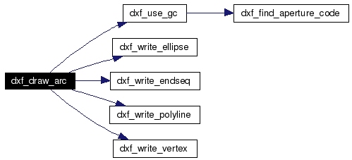 |
|
||||||||||||||||||||||||
|
Draw a line.
The usual drawing functions.
Definition at line 4005 of file dxf.c. References DXF_COLOR_BYBLOCK, DXF_DEFAULT_LAYER, DXF_DEFAULT_LINETYPE, dxf_use_gc(), dxf_write_endseq(), dxf_write_polyline(), dxf_write_vertex(), DXF_X, DXF_Y, OCTAGON, ROUND, and SQUARE. Here is the call graph for this function: 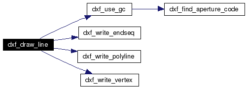 |
|
||||||||||||||||||||||||
|
Draw a rectangle.
The usual drawing functions.
Definition at line 3767 of file dxf.c. References DXF_COLOR_BYBLOCK, DXF_DEFAULT_LAYER, DXF_DEFAULT_LINETYPE, dxf_write_endseq(), dxf_write_polyline(), dxf_write_vertex(), DXF_X, and DXF_Y. Here is the call graph for this function: 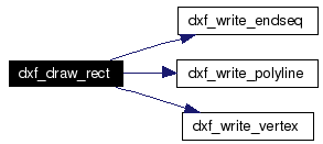 |
|
||||||||||||
|
Sort drills (holes).
Definition at line 3220 of file dxf.c. References DxfPendingDrills::diam, DxfPendingDrills::x, and DxfPendingDrills::y. Referenced by dxf_set_layer(). |
|
|
Print Xrefs to DXF file.
Generate a file in the AutoCAD R14 DXF format for insertion of 3D models as external references (Xref's). Definition at line 2720 of file dxf.c. References _DxfList::descr, dxf_clean_string(), DXF_COLOR_BYLAYER, DXF_DEFAULT_LAYER, DXF_DEFAULT_LINETYPE, DXF_DEFAULT_XREF_PATH_NAME, dxf_insert(), dxf_write_block(), dxf_write_comment(), dxf_write_endsection(), dxf_write_eof(), dxf_write_header(), dxf_write_insert(), dxf_write_section(), dxf_xy_to_angle(), and _DxfList::next. Here is the call graph for this function: 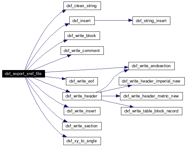 |
|
||||||||||||||||||||
|
Draw a filled circle.
The usual drawing functions.
Definition at line 4760 of file dxf.c. References DxfPendingDrills::diam, DXF_COLOR_BYBLOCK, DXF_DEFAULT_LAYER, DXF_DEFAULT_LINETYPE, dxf_max_pending_drills, dxf_n_pending_drills, dxf_pending_drills, DXF_ROUND, dxf_use_gc(), dxf_write_circle(), DXF_X, DXF_Y, is_drill, DxfPendingDrills::x, and DxfPendingDrills::y. Here is the call graph for this function:  |
|
||||||||||||||||||||
|
Draw a filled polygon.
The usual drawing functions.
The filled polygon is by drawn by a (closed) polyline sequence with (n_coords + 1) vertices and add a SOLID hatch pattern to this polyline.
Definition at line 4861 of file dxf.c. References current_mask, DXF_COLOR_BYBLOCK, DXF_COLOR_BYLAYER, DXF_DEFAULT_HATCH_PATTERN_NAME, DXF_DEFAULT_LAYER, DXF_DEFAULT_LINETYPE, dxf_use_gc(), dxf_write_hatch(), dxf_write_hatch_boundary_path_polyline(), dxf_write_hatch_boundary_path_polyline_vertex(), DXF_X, DXF_Y, and is_mask. Here is the call graph for this function:  |
|
||||||||||||||||||||||||
|
Draw a filled rectangle.
The usual drawing functions.
Definition at line 4977 of file dxf.c. References DXF_COLOR_BYBLOCK, DXF_DEFAULT_LAYER, DXF_DEFAULT_LINETYPE, dxf_write_solid(), DXF_X, and DXF_Y. Here is the call graph for this function:  |
|
||||||||||||
|
Find aperture code.
Search for an appropriate aperture, and if not found, create a new aperture and add it to the list.
Definition at line 525 of file dxf.c. References Apertures::aperture, Aperture::apertureShape, Aperture::apertureSize, curapp, Aperture::dCode, and Apertures::nextAperture. Referenced by dxf_set_layer(), and dxf_use_gc(). |
|
|
Get export options such as filename and filename base.
Returns a set of resources describing options the export or print HID supports. Definition at line 2606 of file dxf.c. References NUM_OPTIONS. Referenced by dxf_do_export(). |
|
|
Find a group for a given layer ??.
Definition at line 849 of file dxf.c. Referenced by dxf_layer_sort(). |
|
||||||||||||||||||||
|
Insert an element in the list of elements.
Definition at line 2633 of file dxf.c. References _DxfList::descr, dxf_string_insert(), _DxfList::next, _DxfList::num, _DxfList::refdes, and _DxfList::value. Referenced by dxf_export_xref_file(). Here is the call graph for this function:  |
|
||||||||||||
|
Sort layers ??.
Definition at line 868 of file dxf.c. References dxf_group_for_layer(). Here is the call graph for this function:  |
|
|
Constructor for the graphic context.
|
|
|
Close DXF layer file.
Definition at line 3042 of file dxf.c. References dxf_write_eof(). Here is the call graph for this function:  |
|
||||||||||||
|
Parse the command line.
Parse HID register attributes and HID command line arguments. |
|
||||||||||||||||
|
Show porgress ?.
|
|
||||||||||||
|
Set a color.
Set the color of the entity. Names can be like "red" or "#rrggbb" or special names like "erase". Always use the "erase" color for removing ink (like polygon reliefs or thermals), as you cannot rely on knowing the background color or special needs of the HID.
|
|
||||||||||||
|
Sets the crosshair.
Which may differ from the pointer depending on grid and pad snap.
|
|
||||||||||||
|
Set the layer with
During redraw or print/export cycles, this is called once per layer (or layer group, for copper layers).
Definition at line 3263 of file dxf.c. References dxf_drill_sort(), dxf_find_aperture_code(), dxf_n_pending_drills, dxf_pending_drills, DXF_X, DXF_Y, is_drill, and ROUND. Here is the call graph for this function:  |
|
||||||||||||
|
Set the line style.
Set the line cap style in the graphic context. |
|
||||||||||||
|
Set the line width.
Set the line width in the graphic context. |
|
|
Show item ?.
|
|
||||||||||||
|
Insert the string to the list of strings.
Definition at line 957 of file dxf.c. References _StringList::next. Referenced by dxf_insert(). |
|
||||||||||||
|
Use the graphic context.
Definition at line 3674 of file dxf.c. References dxf_find_aperture_code(), is_drill, is_mask, ROUND, and SQUARE. Referenced by dxf_draw_arc(), dxf_draw_line(), dxf_fill_circle(), and dxf_fill_polygon(). Here is the call graph for this function:  |
|
|
Special note about the "erase" color: To use this color, you must use this function to tell the HID when you're using it.
Definition at line 3564 of file dxf.c. References current_mask. |
|
||||||||||||||||||||||||||||||||||||||||||||||||||||||||
|
Write DXF output to a file for a block entity.
The
Definition at line 1038 of file dxf.c. References DXF_DEFAULT_LAYER, DXF_DIR_SEPARATOR, and DXF_PAPERSPACE. Referenced by dxf_export_xref_file(). |
|
||||||||||||||||||||||||||||||||||||||||||||||||||||||||||||
|
Write DXF output to a file for a
Definition at line 1155 of file dxf.c. References DXF_COLOR_BYLAYER, DXF_DEFAULT_LAYER, DXF_DEFAULT_LINETYPE, and DXF_PAPERSPACE. Referenced by dxf_fill_circle(). |
|
||||||||||||
|
Write DXF output for a comment string with line termination.
The group code "999" indicates that the following line is a comment string.
Definition at line 1226 of file dxf.c. Referenced by dxf_export_xref_file(). |
|
||||||||||||||||||||||||||||||||||||||||||||||||||||||||||||||||||||||||||||||||
|
Write DXF output to a file for an ellipse entity.
This entity requires AutoCAD version R14 or higher.
Definition at line 1262 of file dxf.c. References DXF_COLOR_BYLAYER, DXF_DEFAULT_LAYER, DXF_DEFAULT_LINETYPE, and DXF_PAPERSPACE. Referenced by dxf_draw_arc(). |
|
|
Write DXF output to a file for an end of section marker.
Definition at line 1340 of file dxf.c. Referenced by dxf_export_xref_file(), and dxf_write_header(). |
|
|
Write DXF output to a file for an end of sequence marker.
No fields.
Definition at line 1367 of file dxf.c. Referenced by dxf_draw_arc(), dxf_draw_line(), and dxf_draw_rect(). |
|
|
Write dxf output to a file for an EOF marker.
Definition at line 1386 of file dxf.c. Referenced by dxf_export_xref_file(), and dxf_maybe_close_file(). |
|
||||||||||||||||||||||||||||||||||||||||||||||||||||||||||||||||||||||||||||||||||||||||||||||||||||||||||||||||
|
Write DXF output to a file for a hatch entity. This entity requires AutoCAD version R14 or higher.
Definition at line 1409 of file dxf.c. References DXF_COLOR_BYLAYER, DXF_DEFAULT_LAYER, DXF_DEFAULT_LINETYPE, and DXF_PAPERSPACE. Referenced by dxf_fill_polygon(). |
|
||||||||||||||||||||||||
|
Write DXF output to a file for a hatch boundary path polyline. This entity requires AutoCAD version R14 or higher.
Definition at line 1513 of file dxf.c. Referenced by dxf_fill_polygon(). |
|
||||||||||||||||||||
|
Write DXF output to a file for a hatch boundary polyline entity. This entity requires AutoCAD version R14 or higher.
Definition at line 1544 of file dxf.c. Referenced by dxf_fill_polygon(). |
|
|
Write DXF output to a file for a DXF header derived from a default header template file if available. If no default header template file is available, generate one depending on the dxf_metric variable.
Write down a DXF header based on values derived from a default header template file (in pcb/src/hid/dxf/template directory).
Definition at line 2171 of file dxf.c. References dxf_write_endsection(), dxf_write_header_imperial_new(), dxf_write_header_metric_new(), and dxf_write_table_block_record(). Referenced by dxf_export_xref_file(). Here is the call graph for this function: 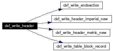 |
|
|
Write DXF output to a file for a imperial DXF header.
Fall back for if no default imperial header template file exists in the pcb/src/hid/dxf/template directory.
Definition at line 1588 of file dxf.c. Referenced by dxf_write_header(). |
|
|
Write DXF output to a file for a metric DXF header.
Fall back for if no default metric header template file exists in the pcb/src/hid/dxf/template directory.
Definition at line 1638 of file dxf.c. Referenced by dxf_write_header(). |
|
||||||||||||||||||||||||||||||||||||||||||||||||||||||||||||||||||||||||||||||||||||
|
Write DXF output to a file for an insert entity.
Definition at line 2238 of file dxf.c. References DXF_COLOR_BYLAYER, DXF_DEFAULT_LAYER, DXF_DEFAULT_LINETYPE, and DXF_PAPERSPACE. Referenced by dxf_export_xref_file(). |
|
||||||||||||||||||||||||||||||||||||||||||||||||||||||||||||||||||||||||||||||||||||||||||||
|
Write DXF output to a file for a polyline entity.
Following the Polyline header is a sequence of
Definition at line 2350 of file dxf.c. References DXF_COLOR_BYLAYER, DXF_DEFAULT_LAYER, DXF_DEFAULT_LINETYPE, and DXF_PAPERSPACE. Referenced by dxf_draw_arc(), dxf_draw_line(), and dxf_draw_rect(). |
|
||||||||||||
|
Write DXF output to a file for a section marker.
Definition at line 2449 of file dxf.c. Referenced by dxf_export_xref_file(). |
|
||||||||||||||||||||||||||||||||||||||||||||||||||||||||||||||||||||||||||||||||
|
Write DXF output to a file for a solid entity.
Definition at line 2472 of file dxf.c. References DXF_COLOR_BYLAYER, DXF_DEFAULT_LAYER, DXF_DEFAULT_LINETYPE, and DXF_PAPERSPACE. Referenced by dxf_fill_rect(). |
|
|
Write DXF output to a file for a
The DXF
Definition at line 1131 of file dxf.c. Referenced by dxf_write_header(). |
|
||||||||||||||||||||||||||||||||||||||||||||||||||||||||||||||||
|
Write DXF output to a file for a polyline vertex entity.
Definition at line 2534 of file dxf.c. References DXF_COLOR_BYLAYER, DXF_DEFAULT_LAYER, DXF_DEFAULT_LINETYPE, and DXF_PAPERSPACE. Referenced by dxf_draw_arc(), dxf_draw_line(), and dxf_draw_rect(). |
|
||||||||||||
|
Convert pcb x,y coordinates to an angle relative to (0.0, 0.0).
Definition at line 885 of file dxf.c. Referenced by dxf_export_xref_file(). |
|
|
Call this as soon as possible from main(). Initialise and register the DXF HID. No other HID calls are valid until this is called. |
|
|
RCS identification string.
|
|
|
Current mask.
Definition at line 484 of file dxf.c. Referenced by dxf_fill_polygon(), and dxf_use_mask(). |
|
|
DXF file with layer color BYBLOCK (or by layer number).
|
|
|
File name of layer DXF files.
|
|
|
File name suffix for layer files.
|
|
|
File name of DXF header template file.
|
|
|
Record with all values of the DXF HID.
|
|
|
Every DXF entity has a unique identifier (per DXF file).
|
|
|
The last X coordinate.
|
|
|
The last Y coordinate.
|
|
|
Layer name.
|
|
|
Maximum number of pending drills (holes).
Definition at line 514 of file dxf.c. Referenced by dxf_fill_circle(). |
|
|
DXF file with output in mm (not mils).
|
|
|
Number of pending drill (holes).
Definition at line 509 of file dxf.c. Referenced by dxf_fill_circle(), and dxf_set_layer(). |
|
|
Initial value:
{
  {"dxffile", "DXF layer filename base", HID_String, 0, 0, {0, 0, 0}, 0, 0},
#define HA_dxffile
  {"metric", "export DXF files in mm", HID_Boolean, 0, 0, {0, 0, 0}, 0, 0},
#define HA_metric
  {"layer color BYBLOCK", "export entities in color BYBLOCK", HID_Boolean, 0, 0, {0, 0, 0}, 0, 0},
#define HA_color_byblock
  {"xrefs", "export a DXF file with xrefs", HID_Boolean, 0, 0, {0, 0, 0}, 0, 0},
#define HA_xrefs
  {"xreffile", "DXF Xrefs filename", HID_String, 0, 0, {0, 0, 0}, 0, 0},
#define HA_xreffile
  {"verbose", "verbose output (comments)", HID_Boolean, 0, 0, {0, 0, 0}, 0, 0},
#define HA_verbose
}
|
|
|
Pending drill (holes).
Definition at line 504 of file dxf.c. Referenced by dxf_fill_circle(), and dxf_set_layer(). |
|
|
Used for HID attributes (exporting and printing, mostly).
HA_boolean uses int_value, HA_enum sets int_value to the index and str_value to the enumeration string. |
|
|
DXF file with verbose output (to contain DXF comments).
|
|
|
File name of Xref (blocks) DXF file.
|
|
|
DXF file with xrefs needed.
|
|
|
File pointer for DXF layer files.
|
|
|
Entity is a drill (hole).
Definition at line 489 of file dxf.c. Referenced by dxf_fill_circle(), dxf_set_layer(), and dxf_use_gc(). |
|
|
Layer is a mask.
Definition at line 479 of file dxf.c. Referenced by dxf_fill_polygon(), and dxf_use_gc(). |
|
|
Line count ??.
|
 1.4.6
1.4.6